
Hydraulic transients in pipelines occur when the steady-state conditions at a given point in the pipeline start changing with time, e.g., shutdown of a valve, failure of a pump, etc. A pumping system must be designed to withstand the surges during transient conditions.
When a centrifugal pump is started by a synchronous electric motor against an open discharge valve, the torque varies approximately as the square of the rotational speed, provided that the specific speed of the pump is sufficiently low. Slurry pumps normally lie in the specific speed range of Ns < 3500 or ns < 0.01. Most synchronous motors are able to deliver sufficient starting torque to get the pump up to speed within an acceptable time. For an oversized drive, the inertia of the impeller is large compared to that of the motor. It is advisable to calculate the angular acceleration of the rotating assembly and hence determine the torque on the pump shaft. It has been known for shafts to fail in torsion from this cause, especially in pumps that start and stop often.
The variations in power and torque during start-up depend on the condition of the pipeline. Consider a case where the system is started fully, as shown by system-A in figure a. The initial system characteristic is now represented by System A in Fig. 15.a. In this case, flow commences only when the impeller has accelerated to a speed sufficient to generate a head that will overcome the static requirement.
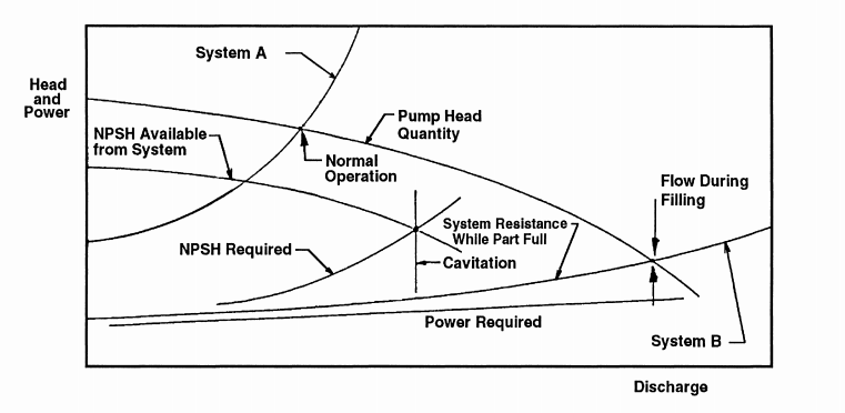
Figure a. Pump and system characteristics during pipeline filling
Consider next the case where the system is not completely full on start-up. The initial system characteristic is now represented by System B in Fig. 15.a. The pump will run up to design rotational speed, so that the head-discharge characteristic runs up to the System B head-discharge characteristic. With the partially filled line, the initial discharge and power will be greater than during normal steady operation. It is not uncommon to find electric motor drives burned out from the high power required during system filling.
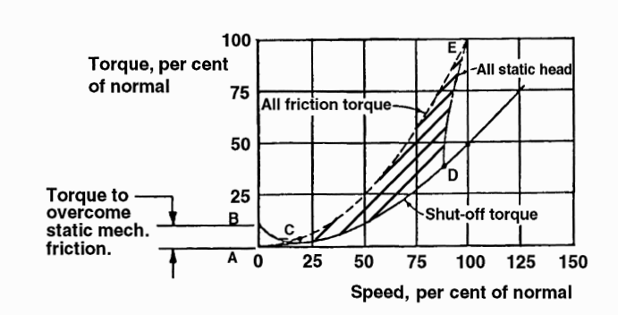
Figure b. Variation of torque with speed for pump starting up on a system initially full
Figure b. shows the corresponding variation of torque with speed for pump starting up on a system initially full. The initial torque arises from mechanical friction, so that the pump starting condition corresponds to point B rather than point A. Around point C, at a speed which depends on the pump size but is typically in the range 10-20% of full speed, the torque imparted to the fluid takes over as the dominant component. For the extreme case of a system dominated by static lift, there is no flow until the pump reaches the speed corresponding to point D. The discharge increases rapidly and therefore the torque also increases, along the curve DE. At the other extreme, where there is no static lift so that the system resistance arises solely from friction, the flow increases steadily as the impeller comes up to full speed. The torque therefore increases steadily, along the curve CE. So, if a synchronous motor is used, the impeller will be accelerated up to full rotational speed most rapidly in a system containing a large proportion of static lift.
The NPSH required by a pump increases with discharge. Given a constant static suction head, increasing friction losses in the suction pipe causes the NPSH available to decrease with increasing Q. In extreme cases, like when flow during line filling exceeds that at which the NPSH available falls below the NPSH required, cavitation will be severe enough to generate a vapor pocket.
The fluctuations in the size and concentration of solids in slurry can also lead to fluctuations in operating conditions. A sharp increase in the concentration of the slurry causes a surge in flow and therefore causes a power surge, possibly leading to cavitation and water hammer. Sudden reduction in slurry concentration causes a reduction in flow so that, if the system is operating close to the deposit velocity, the solids can settle out.
Sudden power failure is always a risk, and can present major problems in field applications. If the line is running at high velocity, sudden loss of torque to the pump can cause the pressure in the pump to fall sharply, to the point where a vapor pocket forms and a water hammer results.
A water hammer is a pressure surge caused when slurry in motion is forced to stop or change direction suddenly. A pressure wave moves through a fluid at a characteristic sonic velocity, or “celerity” which depends on the fluid properties. In a pipeline, the elasticity of the walls reduces the celerity of the disturbance, denoted by a. A typical value for a steel pipe filled with water (or aqueous slurry) is about 1000 m/s. As given by the elastic-column model, the rise in pressure generated by a change in velocity is:

where ΔV is the change in velocity. In terms of head, the transient rise is:
Because the ratio a/g is approximately 100, a head transient in a pipeline is about 100 times the velocity change. Both equations apply to any rapid change in operating conditions.
Rapid opening and closing of valves is always to be avoided. However, vapor pockets can also be caused by other types of maloperations, which can lead to severe water hammer. Maloperation of the pump at the feed end of a long line can set up a pressure wave which travels along the line until it meets the first change in section. This is typically the next pump, which may suffer more or less severe damage. In extreme cases, the water hammer explodes the pump shell.
We aim to provide responsive service. Please contact us and
we will do our best to address your query: