A rheogram can be defined as the relationship between shear stress (τ) and strain rate (du/dy). The simplest rheogram, with a single rheological parameter, µ, is that of a Newtonian liquid, such as water, where the following equation is obeyed:
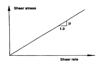
Here, µ represents the dynamic viscosity of the fluid. The rheogram of a Newtonian fluid is a straight line that passes through the origin and has a slope µ as shown in the figure below.

Figure: Rheogram for Newtonian fluid
The next step upward in complexity is represented by two parameter models. True fluids have a rheogram that passes through the origin but may not be a straight line. Hence, the power law model may be employed with parameters k and n:
For slurry flows, the usual behaviour, called pseudo-plastic, corresponds to n< 1.
For a plastic material, the rheogram does not pass through the origin, and no strain rate occurs until the shear stress exceeds some yield value τy. A simple two-parameter model called the Bingham plastic is often employed to quantify this behaviour. Its rheogram is linear, passing through the Bingham yield stress τB at du/dy = 0 and having a slope ηB that is called 'plastic viscosity', or 'tangent viscosity'. Thus,
If a material shows non-linear behaviour at low shear rates, a better fit may be obtained with the Casson model, given by the equation:
Where τc is the Casson yield stress and ηc is the Casson viscosity.
The introduction of additional parameters may seem to improve the fit of the model to the rheological data, but in practice calibration of a three-parameter model is very difficult. One example of three-parameter model that used is the yield-power-law or Herschel-Bulkley model, with the equation:
This model simplifies to the power-law model if yield point shear stress, τy = 0, and to the Bingham model if n = 1 and if both these conditions apply, it simplifies to the Newtonian model.
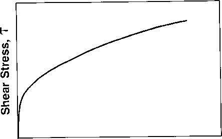
For non-Newtonian fluids, rheograms are not so simple. Rheogram of non-Newtonian fluids do not show a direct proportionality between shear stress and shear rate. Viscosity (the ratio of shear stress to shear rate) varies with shear rate. An example of a non-Newtonian shear stress/shear rate relationship is shown in the figure below. Here, the rheogram does not pass through the origin and is not straight.

Figure: Rheogram for phosphate slime.
Rotational viscometers and tube viscometers are used to obtain the data points required for plotting the rheogram, of which the latter is preferred. Rotational viscometers introduce much larger uncertainties than tube viscometers. Conditions within the tube viscometer are geometrically similar to the condition in the pipeline. So, scale-up techniques can be applied without the intermediary of a rheological model. In a tube viscometer, the measured pressure gradient dp/dx gives a direct evaluation of the wall shear stress τ0. For the construction of rheogram, the shear rate (du/dy) must be evaluated at the wall. This shear rate can be obtained from the Vm.
The rheological model is first selected and is fitted to the data points of the rheogram, and the specific values of parameters such as ty, k, and n are determined. It is important to know whether the flow in the prototype pipeline will be laminar or turbulent, and to be able to predict pressure drop in terms of mean velocity. This can be determined by integration of the rheological-model equation. An alternative to this method is the use of a tube viscometer. By making use of tube viscometer, it is possible to extend the experimental range into the turbulent flow region. Since the turbulent-flow data can be scaled directly to prototype size, this technique is recommended.
We aim to provide responsive service. Please contact us and
we will do our best to address your query: