
The shear rate ( ) is the rate of change of velocity at which one layer of fluid passes over an adjacent layer. In physics, it is defined as the rate at which a progressive shearing deformation is applied to some material. The SI unit of measurement for shear rate is s-1 or “reciprocal seconds”.
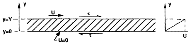
The above illustrates two flat parallel plates. The plate where y = 0 is stationary while the plate at y = Y is moving with velocity u. Here, y is the distance between two parallel plates.
For a simple fluid like water, is linearly proportional to . This type of relationship defines a 'Newtonian fluid', and the constant of proportionality is known as the 'shear viscosity' (or simply the viscosity) and will be denoted by . Thus:
where, du/dy is the shear rate of the fluid. This is known as the constitutive equation of a Newtonian fluid.
Shear rate values range from zero at the pipe axis to a maximum value (0) at the pipe wall. For construction of usual form of rheogram, the shear rate must also be evaluated at the wall. This shear rate can be obtained from the mean velocity Vm (discharge divided by pipe cross-sectional area). The nominal wall shear rate is given by:
Where:
is the shear rate in reciprocal seconds;The mean velocity Vm is related to the volumetric flow rate Q by:
Here, A represents the cross-sectional area of the pipe.
For laminar Newtonian flow in a tube, the rheogram is equivalent to a plot of τ0 versus 8Vm/D, which will be a straight line passing through the origin and having a slope equal to the viscosity µ. For non-Newtonian fluids, the value of du/dy at the wall is no longer equal to 8Vm/D, but it is proportional to it, as determined by Rabinowitsch (1929) and Mooney (1931). In applying the Rabinowitsch-Mooney technique, the first step is to plot τ0 versus 8Vm/D on logarithmic co-ordinates. The slope of this plot is denoted by n'. The true wall shear rate for non-Newtonian slurry is given by:
For a non-Newtonian which follows the power-law model, n' would be constant. For other types of behaviour, n' varies along the rheogram.
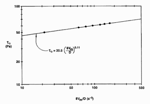
Figure a: Logarithmic plot of τ0 versus 8Vm/D
Let us see a logarithmic plot of τ0 versus 8Vm/D for phosphate-slime slurry tested at the GIW Hydraulic Laboratory in a pipe with an internal diameter of 203 mm. Here, n' represents the slope of this plot. n' varies along the rheogram, but can usually be taken as approximately constant over considerable portions of the curve of τ0 versus 8Vm/D. For each such portion of the curve, n' is found and used to calculate (3n'+l)/4n'. As demonstrated by Rabinowitsch and Mooney, this ratio represents the proportionality constant between 8Vm/D and the strain rate at the wall (Metzner, 1961). The rheogram, i.e. τ0 versus du/dy, can thus be obtained from the tube data by using τ0 in place of τ and
γ=8VmD3n'+14n'
in place of du/dy. For the special case of a Newtonian fluid, both n' and the ratio (3n' + 1)/4n' are unity.
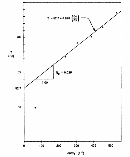
This technique has been applied to the data plotted in Fig. a to produce the rheogram shown in Fig. b. From Fig. a, the slope n' of the logarithmic plot was found to be 0.110, and hence the scaling ratio (3n' + 1)/4n' is 3.02. Thus, du/dy for each point is obtained by multiplying 8Vm/D by 3.02, resulting in the rheogram plotted in Fig. b. On the Cartesian axes of this figure, all the points except the lowest can be represented by a straight line. The intercept of 52.7 Pa and the slope of 0.020 Pa-s were calculated. This system of employing 8Vm/D is more convenient in scaling up to larger pipe sizes.
We aim to provide responsive service. Please contact us and
we will do our best to address your query: